
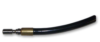
Soft flexible conduit - smooth feeding
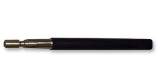
Rigid steel-reinforced conduit - smooth feeding
Overview
D/F Machine Specialties delivers the performance and reliability you need to minimize your production costs while maximizing welding efficiency! Many large manufacturers with semi-automatic, automatic, and robotic assembly lines have discovered the advantages of using D/F Machine Specialties welding products; dramatically reducing down time for tip changes, therefore increasing productivity. D/F has two different styles of conduits (casings, whips), flexible and semi-rigid steel reinforced guide conduits for a multitude of push welding applications.
Our MIG wire casings are designed with a flexible polymer core for comfort and flexibility, or with a steel-reinforced piano-wound core for hard and cored wire welding.
Black Extra Flexible Conduit - Flexibility and Feedability
Our most flexible conduit displays exceptional wear characteristics and very low drag coefficient. Perfect for robotics, gantry, linear, or any application where a tighter radius is required, or for shorter distances where feeding is not an issue. They are available in pre-cut lengths of 2 ft to 15 ft (61cm to 4.6m). These flexible wire guide conduits are for all types of arc welding. These casings accept the full line of D/F's nylon liners for aluminum and inconel welding and steel-wound liners for hard/cored/stainless welding. "Get your welding wire to the feeder... Fast and Easy". They are tested and proven to have the lowest friction coefficient in the industry and have a standard spatter resistant outer jacket.
Rubber Coated Black Steel Wound-Reinforced Rigid Conduit - Surprisingly Flexible yet Increased Support and Feedability
Our most rigid conduit displays exceptional wear characteristics and very low drag coefficient. Perfect for semi-automatic, automatic, and robotic aluminum welding where more support and feedability is required, or for longer distances where feeding is an issue. What is beautiful about these single piece steel-reinforced conduits is not only do they have the steel-wound liner built into them, but if you order the largest size steel-wound conduit for 7/64"-1/8" hard/cored/stainless wires, you can also insert D/F's full line of nylon liners for aluminum and inconel welding and steel-wound liners for hard/cored/stainless welding. This is the heaviest-duty liner system available with the most superior durability and feedability for extreme duty cycles. They are available in pre-cut lengths of 2 ft to 15 ft (61cm to 4.6m). They are tested and proven to have the lowest friction coefficient in the industry and have a standard spatter resistant outer jacket.
We can make any length casing (conduit, whip), in any quantity, for wires of .030", .035", .045", .052", 1/16", 3/64", 5/64", 3/32", 1/8" and other diameters. Each requirement is quoted quickly and accurately to meet your needs.
D/F casings are available in common lengths to 25' (7.6 m) for all wire sizes and most every robotic and manual welding application. We will also do specials in any length and size needed to get your job done!
Please Note: All D/F casings require an appropriate MIG wire liner unless using the single-piece, steel-wound casing as a liner. See the MIG Torch Liners page for the different choices. D/F manufactures a complete line of feeder adapters that can connect to the conduits for connecting to all manufacturers' wire feeders. See the MIG Torch Feeder Adapters page for the different choices.
Ordering Information
Soft Flexible Polymer Casing / Conduit / Whip
| LENGTH | .030"-3/32" (.8mm-2.4mm) (REQUIRES LINER) |
|---|---|
| 2 Ft. | 46370-2 |
| 3 Ft. | 46370-3 |
| 4 Ft. | 46370-4 |
| 5 Ft. | 46370-5 |
| 6 Ft. | 46370-6 |
| 7 Ft. | 46370-7 |
| 8 Ft. | 46370-8 |
| 9 Ft. | 46370-9 |
| 10 Ft. | 46370-10 |
| 11 Ft. | 46370-11 |
| 12 Ft. | 46370-12 |
| 13 Ft. | 46370-13 |
| 14 Ft. | 46370-14 |
| 15 Ft. | 46370-15 |
| 18 Ft. | 46370-18 |
Rigid Steel-Reinforced Casing / Conduit / Whip
| LENGTH | .030"-.035" (.8mm-.9mm) |
.035"-.045" (.9mm-1.2mm) |
.045"-1/16" (1.2mm-1.6mm) |
5/64"-3/32" (2mm-2.4mm) |
7/64"-1/8" (2.8mm-3.2mm) |
|---|---|---|---|---|---|
| 2 Ft. | 46350-2 | 46420-2 | 46440-2 | 46460-2 | 46480-2 |
| 3 Ft. | 46350-3 | 46420-3 | 46440-3 | 46460-3 | 46480-3 |
| 4 Ft. | 46350-4 | 46420-4 | 46440-4 | 46460-4 | 46480-4 |
| 5 Ft. | 46350-5 | 46420-5 | 46440-5 | 46460-5 | 46480-5 |
| 6 Ft. | 46350-6 | 46420-6 | 46440-6 | 46460-6 | 46480-6 |
| 7 Ft. | 46350-7 | 46420-7 | 46440-7 | 46460-7 | 46480-7 |
| 8 Ft. | 46350-8 | 46420-8 | 46440-8 | 46460-8 | 46480-8 |
| 9 Ft. | 46350-9 | 46420-9 | 46440-9 | 46460-9 | 46480-9 |
| 10 Ft. | 46350-10 | 46420-10 | 46440-10 | 46460-10 | 46480-10 |
| 11 Ft. | 46350-11 | 46420-11 | 46440-11 | 46460-11 | 46480-11 |
| 12 Ft. | 46350-12 | 46420-12 | 46440-12 | 46460-12 | 46480-12 |
| 13 Ft. | 46350-13 | 46420-13 | 46440-13 | 46460-13 | 46480-13 |
| 14 Ft. | 46350-14 | 46420-14 | 46440-14 | 46460-14 | 46480-14 |
| 15 Ft. | 46350-15 | 46420-15 | 46440-15 | 46460-15 | 46480-15 |
Old D/F Casings
| DESCRIPTION | WIRE SIZE | 2 FT. | 3 FT. | 4 FT. | 5 FT. | 6 FT. | 7 FT. | 8 FT. | 10 FT. | 12 FT. | 15 FT. |
|---|---|---|---|---|---|---|---|---|---|---|---|
| Casing Assembly (Flexible) Select Liner | .030" | 14440 | 14441 | 14442 | 14443 | 12291 | 12292 | 12285 | 12286 | 12287 | 12290 |
| .035" | 14444 | 14445 | 14446 | 14447 | 16173 | 16561 | 13565 | 13751 | 13757 | 13752 | |
| Casing Assembly (Reinforced) Select Liner | .035"-.045" | 16735 | 16736 | 16737 | 16738 | 16739 | 16740 | 16512 | 16988 | 15991 | 16055 |
| .045"-1/16" | 15750 | 15751 | 15752 | 15753 | 15754 | 15755 | 16513 | 12380 | 12383 | 12386 | |
| 5/64"-3/32" | 15729 | 15730 | 15731 | 15732 | 15733 | 15734 | 15735 | 12441 | 12449 | 12443 | |
| 7/64"-1/8" | 15740 | 15741 | 15742 | 15743 | 15744 | 15745 | 16515 | 12445 | 12448 | 12446 |
Installing A New Wire Conduit / Casing / Whip
- Be sure the MIG Gun cables are arranged in a straight line, free from twists, when installing or removing a wire conduit/casing & liner.
- Remove the old liner by first removing the MIG guns contact tip.
- Pull the old wire liner out of the conduit/casing assembly from the feeder connector or feeder adapter plug end.
- Be sure the MIG Gun cables are arranged in a straight line, free from twists, when installing or removing a wire conduit/casing & liner.
- Make sure the conduit/casing and feeder adapter have been removed from the drive rolls.
- Loosen any Allen screws or body screws in the torch inner body or docking spool and pull the old conduit/casing out of the assembly from the feeder adapter end.
- To install a new wire conduit/casing, first inspect the conduit/casing for cuts or damage. Start from the feeder adapter end of the assembly and begin pushing the conduit/casing through the sheath and/or cable assembly and into the gun. If the conduit/casing should lodge along the way, gently whip or work the cable assembly to aid forward movement.
- When the wire conduit/casing stop meets the end of the inner body or docking spool the Allen screw must be securely tightened onto the conduit/casing to prevent its backward movement or pumping action.
- To install a new liner, start from the feeder adapter end of the assembly and begin pushing the liner through the feeder adapter & conduit/casing and into the gun or torch. If the liner should lodge along the way, gently whip or work the conduit/casing & liner assembly to aid forward movement. Sometimes on longer conduits/casings and liners it may take 2 people together; one on each end to rotate and twist the conduit/casing to get the liner trough the torch.
- Replace gas diffuser, contact tip, and nozzle.
- Tighten the Allen screw in the inner body or docking spool.