
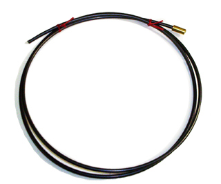
Nylon Aluminum Wire MIG Liner
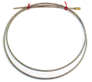
Steel / Hard / Cored Wire MIG Liner
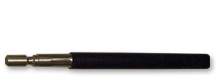
Rigid steel-reinforced conduit - smooth feeding
Overview
D/F Machine Specialties delivers the performance and reliability you need to minimize your production costs while maximizing welding efficiencies! Many large manufacturers with semi-automatic, automatic, and robotic assembly lines have discovered the advantages of using D/F Machine Specialties welding products; dramatically reducing down time for tip changes, therefore increasing productivity. D/F has two different styles of liners (whips), steel-wound music wire for hard/cored/stainless wires, and the supportive nylon liner for inconel and aluminnum, both for a multitude of push applications.
For steel welding, the usual practice is to use a helically wound steel liner with v-groove drive rolls, but for aluminum, this type of liner would scratch the soft aluminum wire and scrape off shavings. It will also contaminate the welds and cause terrible feeding issues. So, when welding aluminum make sure to find a liner that is made of nylon. Nylon materials are recommended to reduce friction and eliminate wire shaving. When welding with aluminum wire you must have U-Groove drive rolls. You cannot weld aluminum with V-Groove drive rolls. V-groove drive rolls will change the shape of the wire by flattening the wire resulting in terrible feeding issues. Also, the tension on the drive roll should be reduced compared to the typical setting for steel to prevent crushing of the aluminum wire during feeding.
Wire Inlet Guides
Similarly, for aluminum welding, wire guides also should be composed of nylon rather than steel. Again, friction is reduced and wire shaving is virtually eliminated.
Our MIG steel liners are precision wound to stringent standards for excellent fit and long life. D/F liners are available in high carbon music wire for smooth wire feed and long life. D/F Machine Specialties also manufactures a complete line of soft plastic liners for Aluminum and Inconel wire welding. We can make any length liner, in any quantity, for wires of .030", .035", .045", .052", 1/16", 3/64", 5/64", 3/32", 7/64", 1/8" and other diameters. Each requirement is quoted quickly and accurately to meet your needs.
Our MIG wire liners are designed with a steel-reinforced piano-wound core for hard and cored wire welding. We also have a heavy duty, rubber-coated, steel-reinforced liner.
Rubber Coated Black Steel Wound-Reinforced Rigid Liner/Conduit - Surprisingly Flexible yet Increased Support and Feedability
Our most rigid conduit displays exceptional wear characteristics and very low drag coefficient. Perfect for semi-automatic, automatic, and robotic aluminum welding where more support and feedability is required, or for longer distances where feeding is an issue. What is beautiful about these single piece steel-reinforced conduits is not only do they have the steel-wound liner built into them, but if you order the largest size steel-wound conduit for 7/64"-1/8" hard/cored/stainless wires, you can also insert D/F's full line of nylon liners for aluminum and inconel welding and steel-wound liners for hard/cored/stainless welding. This is the heaviest-duty liner system available with the most superior durability and feedability for extreme duty cycles. By using the single-piece Rubber Coated Black Steel Wound-Reinforced Rigid Liner/Conduit (46480-X) you can now run wires from 5/64"-1/8" in it as a liner, or you can use either D/F's steel-wound liner or nylon liner for sizes .030"-3/32". This enables customers the ability to run the full spectrum of wires of .030"-1/8" through one conduit and liner system. They are available in pre-cut lengths of 2 ft to 15 ft (61cm to 4.6m). They are tested and proven to have the lowest friction coefficient in the industry and have a standard spatter resistant outer jacket.
D/F casings are available in common lengths to 25' (7.6 m) for all wire sizes and most every robotic and manual welding application. We will also do specials in any length and size needed to get your job done!
Please Note: If a casing/conduit is needed for support of a torch liner, see the D/F MIG Casings/Conduits/ Whips page for the different choices.
Ordering Information
Nylon MIG Liners for Aluminum Wire
| LENGTH | .030"-.035" AL (.8mm-.9mm) |
3/64" AL (1.2mm) |
1/16" AL (1.6mm) |
3/32" AL (2.4mm) |
|---|---|---|---|---|
| 2 Ft. | 47027-2 | 47023-2 | 47024-2 | 47025-2 |
| 3 Ft. | 47027-3 | 47023-3 | 47024-3 | 47025-3 |
| 4 Ft. | 47027-4 | 47023-4 | 47024-4 | 47025-4 |
| 5 Ft. | 47027-5 | 47023-5 | 47024-5 | 47025-5 |
| 6 Ft. | 47027-6 | 47023-6 | 47024-6 | 47025-6 |
| 8 Ft. | 47027-8 | 47023-8 | 47024-8 | 47025-8 |
| 9 Ft. | 47027-9 | 47023-9 | 47024-9 | 47025-9 |
| 10 Ft. | 47027-10 | 47023-10 | 47024-10 | 47025-10 |
| 11 Ft. | 47027-11 | 47023-11 | 47024-11 | 47025-11 |
| 12 Ft. | 47027-12 | 47023-12 | 47024-12 | 47025-12 |
| 13 Ft. | 47027-13 | 47023-13 | 47024-13 | 47025-13 |
| 14 Ft. | 47027-14 | 47023-14 | 47024-14 | 47025-14 |
| 15 Ft. | 47027-15 | 47023-15 | 47024-15 | 47025-15 |
| 18 Ft. | 47027-18 | 47023-18 | 47024-18 | 47025-18 |
MIG Liners for Steel / Hard / Cored Wire
| LENGTH | .030"-.035" (.8mm-.9mm) |
.035"-.045" (.9mm-1.2mm) |
.045"-1/16" (1.2mm-1.6mm) |
|---|---|---|---|
| 2 Ft. | 47020-2 | 47021-2 | 47022-2 |
| 3 Ft. | 47020-3 | 47021-3 | 47022-3 |
| 4 Ft. | 47020-4 | 47021-4 | 47022-4 |
| 5 Ft. | 47020-5 | 47021-5 | 47022-5 |
| 6 Ft. | 47020-6 | 47021-6 | 47022-6 |
| 8 Ft. | 47020-8 | 47021-8 | 47022-8 |
| 9 Ft. | 47020-9 | 47021-9 | 47022-9 |
| 10 Ft. | 47020-10 | 47021-10 | 47022-10 |
| 11 Ft. | 47020-11 | 47021-11 | 47022-11 |
| 12 Ft. | 47020-12 | 47021-12 | 47022-12 |
| 13 Ft. | 47020-13 | 47021-13 | 47022-13 |
| 14 Ft. | 47020-14 | 47021-14 | 47022-14 |
| 15 Ft. | 47020-15 | 47021-15 | 47022-15 |
| 18 Ft. | 47020-18 | 47021-18 | 47022-18 |
Old D/F Liners
| DESCRIPTION | WIRE SIZE | 2 FT. | 3 FT. | 4 FT. | 5 FT. | 6 FT. | 7 FT. | 8 FT. | 10 FT. | 12 FT. | 15 FT. |
|---|---|---|---|---|---|---|---|---|---|---|---|
| Hard | .030" | - | 14130 | 14131 | 14132 | 16818 | 16819 | 16820 | 12320 | 12321 | 12322 |
| Hard/Cored | .035"-.045" | 16443 | 16444 | 16445 | 16446 | 16447 | 16448 | 16449 | 16407 | 16408 | 16409 |
| Hard/Cored | .045"-1/16" | 16147 | 16148 | 16149 | 16150 | 16151 | 16152 | 16153 | 16119 | 16120 | 16121 |
| Stainless | .035"-.045" | 16154 | 16155 | 16156 | 16157 | 16158 | 16159 | 16160 | 12336 | 12337 | 12338 |
| Stainless | .045"-1/16" | 16501 | 16502 | 16503 | 16504 | 16505 | 16506 | 16507 | 16507 | 16509 | 16510 |
| Aluminum/Inconel | 3/64" | 16883 | 14146 | 14148 | 14150 | 16618 | 16619 | 12410 | 12411 | 12412 | 12413 |
| Aluminum/Inconel | 1/16" | 16834 | 14152 | 14154 | 14156 | 14164 | 16620 | 12401 | 12402 | 12416 | 12404 |
| Aluminum/Inconel | 3/32" | 16835 | 14158 | 14160 | 14162 | 14165 | 16769 | 16602 | 12429 | 12417 | 12426 |
Rigid Steel-Reinforced Casing / Conduit / Whip
| LENGTH | .030"-.035" (.8mm-.9mm) |
.035"-.045" (.9mm-1.2mm) |
.045"-1/16" (1.2mm-1.6mm) |
5/64"-3/32" (2mm-2.4mm) |
7/64"-1/8" (2.8mm-3.2mm) |
|---|---|---|---|---|---|
| 2 Ft. | 46350-2 | 46420-2 | 46440-2 | 46460-2 | 46480-2 |
| 3 Ft. | 46350-3 | 46420-3 | 46440-3 | 46460-3 | 46480-3 |
| 4 Ft. | 46350-4 | 46420-4 | 46440-4 | 46460-4 | 46480-4 |
| 5 Ft. | 46350-5 | 46420-5 | 46440-5 | 46460-5 | 46480-5 |
| 6 Ft. | 46350-6 | 46420-6 | 46440-6 | 46460-6 | 46480-6 |
| 7 Ft. | 46350-7 | 46420-7 | 46440-7 | 46460-7 | 46480-7 |
| 8 Ft. | 46350-8 | 46420-8 | 46440-8 | 46460-8 | 46480-8 |
| 9 Ft. | 46350-9 | 46420-9 | 46440-9 | 46460-9 | 46480-9 |
| 10 Ft. | 46350-10 | 46420-10 | 46440-10 | 46460-10 | 46480-10 |
| 11 Ft. | 46350-11 | 46420-11 | 46440-11 | 46460-11 | 46480-11 |
| 12 Ft. | 46350-12 | 46420-12 | 46440-12 | 46460-12 | 46480-12 |
| 13 Ft. | 46350-13 | 46420-13 | 46440-13 | 46460-13 | 46480-13 |
| 14 Ft. | 46350-14 | 46420-14 | 46440-14 | 46460-14 | 46480-14 |
| 15 Ft. | 46350-15 | 46420-15 | 46440-15 | 46460-15 | 46480-15 |
| 18 Ft. | 46350-18 | 46420-18 | 46440-18 | 46460-18 | 46480-18 |
Liner Removal & Installation - Fitting & Cutting a New Liner
- Be sure the MIG Gun cable is arranged in a straight line, free from twists, when installing or removing a wire liner.
- Remove the old liner by first removing the MIG guns contact tip.
- Pull the old wire liner out of the conduit/casing assembly from the feeder connector or feeder adapter plug end. If you are using a feeder adapter that has an inlet, the inlet must be removed first. If you have any problems removing the liner you may unthread the feeder adapter first this will also back the liner out of the conduit/casing.
- If you know that the old liner is the correct length or is still the original liner that was cut at the factory you may hold the new liner up against the old liner and cut off the new liner to the same size as the old liner.
- Make sure you have a good sharp cut off with no material sticking out!
- To get the correct length of the new liner, insert the liner into the feeder adapter and feed it through the conduit/casing.
- Once again be sure the MIG Gun cable is arranged in a straight line, free from twists, when installing a new wire liner.
- Sometimes on longer conduits/casings and liners it may take 2 people together; one on each end to rotate and twist the conduit/casing to get the liner trough the torch.
- If you have any troubles getting a liner through a torch make sure you have a good sharp cut off and if you have to you can gently sand the end of the liner on a belt sander.
- After the new liner comes out the end of the torch you want to cut the new liner off flush with the end of the copper gas nozzle or Cu gas cup.
- Now you have the overall length of the liner, you still have to take out the length of the contact tip.
- Carefully remove the liner one more time
- After removing the liner hold the gun end of the liner up against the tip
- Cut off the length off the tip plus the set back of the tip (1/8” or 3/8” tip setbacks)
- Now that you have cut off the length of the tip plus the setback you may install the new liner and it will back up into the back of the tip chamfer.
- We always recommend checking the condition of the insulation tube in the front of the torch and collet nut that holds the slip-in tip
- We always recommend replacing the spatter disc/gas diffuser, contact tip, and nozzle, after installing a new liner.
- Tighten the Allen screw in the inner body or docking spool.
- Allen set screws must be securely tightened onto the conduit/casing to prevent its backward movement or pumping action.
More Information About D/F MIG Liners
The liner is both one of the simplest and most important components of a MIG welding gun. Its sole purpose is to guide the wire from the wire feeder, through the casing/conduit and up to the contact tip. If it is not performing this task properly, the gun is virtually worthless.
A number of problems can interfere with a liner’s ability to properly guide the wire through the casing/conduit. When the wire does not feed correctly it can decrease weld quality and in turn lead to increased downtime and expensive rework.
The following is a short guide made to help get the best performance out of your D/F MIG liners and to help troubleshoot problems when they occur.
Optimizing Performance
Proactive maintenance can eliminate problems before they arise and reduce operator downtime, more serious equipment failures, and expensive rework. Checking the condition of the liner and changing it out at regular intervals will leave one less thing to worry about.
Buy Quality
The quality of a liner can also impact welding performance, productivity, and downtime. D/F’s quality liners maintain a consistent inside diameter throughout their length. This is critical because variances as small as a few thousandths of an inch can result in wire feeding problems that require downtime for liner replacement.
Choose the Right Size
To maximize the performance of your D/F MIG equipment, choose the correct liner size liner for the wire being used.
Small diameter welding wires .030”-.045” have relatively low columnar strength, which, when paired with an oversized liner, can cause the wire to wander or drift within the liner. This in turn leads to poor wire feeding and premature liner failure due to excessive wear. Larger diameter welding wires 1/16”-1/8”, though having much higher columnar strength, can still wander inside a liner that is too big, causing uneven wear and groove patterns to cause the wire to not feed smoothly. Just make sure the liner you choose is large enough to feed the welding wire you are using.
Don't Overdo It
D/F MIG gun liners are made from coiled steel music wire which allows the liner to be both rigid and flexible, and lets it guide the wire through a tightly bent casing without kinking. Nevertheless, bending the casing too much can cause poor wire feeding, premature liner wear, and birdnesting.
Troubleshooting
Poor or erratic wire feeding, a loss of amperage or frequent contact tip burnback are all signs of possible liner problems. Unfortunately, because of the time it takes to replace the liner, this is often one of the last components checked during a troubleshooting effort.
Poor Wire Feeding
Erratic or poor wire feeding can result when a liner becomes worn out in certain spots or excessive debris builds up in the liner. Excessive debris can usually be cleared out by removing the wire and forcing compressed air through the liner (without removing it from the casing).
In most cases, a worn out liner will need to be replaced. Changing the liner requires disconnecting the gun from the wire feeder, disassembling the power pin, replacing the old liner and trimming the new one to fit the gun.
Birdnesting
If the welding wire’s path of travel through a MIG gun is blocked while the wire feeder is pushing it, a tangled mess of wire called a birdnest could result. A birdnest can be caused by a liner that is trimmed too short, clogged, or the wrong size (too small or large for the wire diameter). The above section on proper liner replacement describes how birdnesting can result from trimming a liner too short.