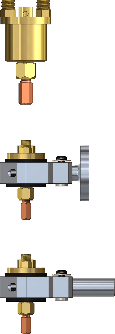
Water-Cooled Gasless Overlay
Mini Torch # 30391
Drawings Accessories More Info
Overview
The Open-Arc Water-Cooled Mini Gasless Overlay Cladding Machine Barrel is recommended for open-arc robotic cladding applications where production demands the maximum durability and quality for multi-surfacing and rebuilding applications. This Mini torch is ideal for single-head machines used with hardfacing and pipe forming applications. They feature single replaceable Water Out & Power Cables to add to the durability and long life of the barrel assemblies. The Open-Arc Mini Machine Barrel is primarily for wire diameters from .045" thru 1/8" (1.143mm thru 3.175mm). The Open-Arc Mini Machine Barrel offers a design that accommodates slip-in tips with a collet. The suggested current level would be approximately 600 amperes (depending on application). Remote mounting is accomplished by an insulated mounting bracket and utilizing a casing/conduit and an adapter to the wire drive.
The D/F torch is famous for the fact, that if it is chilled properly, the welder can grab the chrome front water-cooled barrel (not the copper gas nozzle/cup) of the torch with their bare hand and it will be cold to the touch seconds after welding. With the proper chiller, this can be done even after a 4 hour arc time. Make certain the cooling water supply is at least the minimum flow rate of 1 gallon per minute (for each inner body), at 40 psi (80 psi maximum) with a 6 gallon reservoir and a recommended 30,000 BTU/hr cooling capacity. Gun ratings are affected by shielding gas used, arc time, cooling time and inlet water temperature. Water outlet temperature should not exceed 27°C (80°F). The torch’s water out & power cable is not cooled until the coolant has gone through the torch and out the water out & power cable. If water is not flowing through the D/F torch for at least 1 minute prior to striking an arc, when you apply the power and water hits the “hot” water/out & power cable, you will generate steam. Steam can damage the torches internals in seconds causing a leak. It can also blow out the torches water/out & power cable. A flow switch can be installed after the return line ensuring that coolant is present at the return line prior to striking an arc. When High-Deposition GMAW, high current density, high amperages, preheat, or extended periods of arc time are used, a refrigerated liquid chiller with a larger reservoir is required. Precise temperature control maintains the cooling at a constant 13°C (55°F) temperature, thus prolonging the life of the welding equipment and more specifically extending the service life of the gas nozzle and current tip. D/F Machine Specialties does not manufacture or sell chillers, we only recommend them. Click here to see our recommended chillers.
Each D/F Machine Specialties welding gun is fully assembled and ready to install. In order to make the installation complete, the code number, wire size, wire feeder make/model (Lincoln wire feeders, Miller wire feeders, Tweco wire feeders, ESAB wire feeders, & EURO Quick Disconnect wire feeders), and inlet (as needed) must be specified when ordering. If special welding tools or accessories other than those listed previously are required, please consult with the factory. Get the right feeder adapter connection to fit your MIG wire feeder.
Features
- Water-Cooled Inner Body & Nozzle
- Heavy-Duty Construction for Long-Lasting Durability
- Small Frontal Area for Hard-to-Reach Locations
- Optional #40597 Mounting Bracket with Insulated Bushing for Remote Mounting
Model Explanation
- WCG91-D - Water Cooled Gasless Dual
Model Specifications
| MODEL | CURRENT CAPACITY |
WEIGHT (APPROX.) | COOLING REQUIRED | RECOMMENDED WIRE DIA. RANGE |
INSTRUCTION MANUAL |
|---|---|---|---|---|---|
| WCG91-D | 750 amps | 2.3 lbs | 1 gallon/min | .045"-1/8" (1.2mm-3.2mm) |
WCG91-D |
Barrel Dimensions
| MODEL | LENGTH | DIAMETER OF BODY |
|---|---|---|
| WCG91-D | 4" | 1.5" |
Ordering Information
Complete Barrel Only
| DESCRIPTION | CODE NO. |
|---|---|
| Model WCG91-D Overlay Curved Mini Machine Barrel | 30391 |
Complete Assemblies
| DESCRIPTION | CODE NO. | |||||||
| 4 Ft. | 5 Ft. | 6 Ft. | 7 Ft. | 8 Ft. | 10 Ft. | 12 Ft. | 15 Ft. | |
| WCG91-D | 30391-4 | 30391-5 | 30391-6 | 30391-7 | 30391-8 | 30391-10 | 30391-12 | 30391-15 |
| Add Footage Digit to Item Code Number for Length Required. Example: Require 30391 with 3 Ft. Utilities: 30391-3 |
||||||||
Manuals & Downloads
Instruction Manuals
| TORCH MODELS | DOWNLOAD |
|---|---|
| WCG91-D | WCG91-D |
CAD Files & Drawings
| TORCH MODELS | CODE NO. | CAD FILE | PDF DRAWING |
|---|---|---|---|
| WCG91-D | 30391 | 30391 | 30391 |
Other Documents
| DESCRIPTION | DOWNLOAD |
|---|---|
| Torch Connection Options |
Utility Station #45196
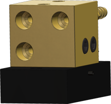
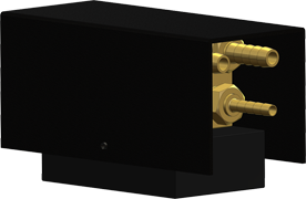
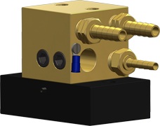
 The D/F Utility Station is required for all D/F torch installations. Typical modern torch setups utilize a unitized cable assembly with a power pin. D/F torches take an alternative approach to the setup. The torches use a separate gas hose, water-in hose, Water Out & Power Cable, and casing/conduit. When one cable goes bad it is simply replaced instead of attaching an entire new unitized cable assembly; a huge cost saver! This is also where the D/F Utility Station comes into play. The gas hose, water-in hose, and Water Out & Power Cable are interfaced with the customer's existing lines via the Utility Station. The D/F torch leads plug into the front (see right) of the Utility Station. Into the back (see below) of the Utility Station go the customer's utilities. Read more on the D/F Utility Station product page.
For more information on proper use of the D/F Utility Station, and to see the various torch connection options, please download the Torch Connection Options one-sheet.


Hardfacing
Hardfacing is gaining more and more importance in the most varied fields of modern engineering. In the case of wear, corrosion and other types of surface attack, the application of hardfacing permits the economical reconditioning of many structural members. Reconditioning may comprise work pieces subjected to metal-to-metal wear. Such as rollers, crane wheels, shafts, rails or which are subjected to metal-to-mineral wear, like building machinery, conveyor screws, excavator bucket edges, etc.
The possibilities of hardfacing not only lie in the field of reconditioning, but more and also in the manufacture of new tools and components. In this manufacturing process, a non-alloyed or low- alloy steel is used as carrier material to which are imparted special properties by welding on a suitable high quality weld metal. Decisive factor in hardfacing is the knowledge of the wear conditions, that is, whether it is a frictional wear caused by metal or minerals, corrosion, cavitation, erosion or temperature. The selection of the welding consumable to be used will depend on these conditions. Besides this, it is most important to know the composition of the base metal to be surfaced, because of the measures likely to be taken, such as preheating and/or post weld treatment.
Depending on the use of the workpiece to be hardfaced, the weld metal shall meet the most varied demands. These can be cited as follows:
- Hardness in the as-welded condition
- Red hardness under thermal loads
- Resistance to metal-to-metal wear
- Abrasion resistance to frictional and grinding wear
- Impact strength
- Corrosion resistance
- Resistance to scaling
In some cases, more than one of these modes of load may occur simultaneously, so that the weld metal must posses the respective properties. Hence, a conscientious selection of the proper weld metal will be a must. Of course, there doesn’t exist a weld metal possessing all these properties in full measure. Nevertheless, in most cases it will be possible to find a satisfactory compromise in practice.
Hardfacing Tools
An interesting field of application in hardfacing is reconditioning of hardened tools, such as shear blades, punching dies, cutting edges, deep-drawing tools, etc. For this purpose, the so-called “step hardening weld method” has proven a success. Welding is carried out in the delayed transformation range which is situated between the perlite and bainite zones of TTT-curves of the steel in question. Thereby, the hardenability of the steel is taken into account. Generally, the temperature range in which welding shall be carried out is from 400°C to 600°C. This means, that step welding is based on the fact that in such steels the transformation of austenitic is clearly delayed within a certain temperature range.
The sequence of operations is as follows:
- Slow heating of the workpiece to its hardening temperature. At this temperature the structure becomes austenitic.
- Cooling to step temperature; that is, to the range in which the delay in austenitic transformation (according to TTT-diagram) is most pronounced.
- Welding the workpiece at this temperature.
- Cooling the workpiece to room temperature in still air or better in oil (50°C to 150°C).
- Tempering to the respective temperature which in the case of high-speed steels lies in the range of 550°C to 570°C.
- Machining the weld area.
For the solution of the many cladding and hardfacing problems, D/F offers a complete line of welding Torches & consumables for flux cored wire electrodes, solid wire electrodes, gas metal arc welding and submerged arc welding fluxes.

