
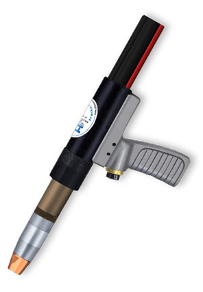
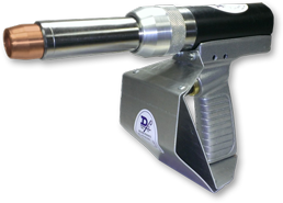
Air-Cooled Pistol Gun (7/16"-3/4" Gas Cup ID)
Drawings Accessories
Overview
The Air-Cooled MIG Pistol Grip Gun comes completely assembled and can be fitted with various nozzle combinations to suit different welding situations. The power cable, electrical and gas services are replaceable. Wire casings are either a single piece type primarily for cored wire, or those with flexible (2-piece) casing and liner combinations for hard and soft wire. These air-cooled pistol guns are offered in several different models. The model PAC employs a slip-in tip fastened by a collet action nut. The model PAT accommodates a threaded current tip. Various front end nozzle body arrangements are offered to cover a broad range of applications. Conversion to the use of a particular nozzle body arrangement is easily accomplished by selecting the desired nozzle body and current tip adapter arrangement.
The air-cooled gun assemblies operate on a current through 400 amperes, contingent on the front end nozzle body being and current tip being used. The model PAC operates on a current level through 260 amperes with a slip-in current tip. The model PAT operates on a current through 400 amperes with CO2, and 260 amperes with argon with a threaded current tip. Gun assemblies will accommodate a wire diameter range of .030” through .062” diameter.
Each D/F gun is fully assembled and ready to install. In order to make the installation complete, the code number, wire size, make/model (Lincoln wire feeders, Miller wire feeders, Tweco wire feeders, ESAB wire feeders, & EURO Quick-Disconnect wire feeders), and inlet as needed must be specified when ordering. If special welding tools or accessories other than those listed previously are required, please consult with the factory. Get the right feeder adapter connection to fit your MIG wire feeder.
Features
- 400 Amp CO2, 260 Amp Argon Current Capacity - 1/0 Power Cable
- Several Nozzle Body Configurations Available
- Heavy Duty Brass Inner Body
- Chrome Plated Brass Front End - Heavy Duty Copper Nozzle
- Standard and Quick-Disconnect Utilities Available
- High Temperature Insulation
Model Explanation
- PAC - Pistol, Air-Cooled, Collet Action (Slip-In Tip)
- PAT - Pistol, Air-Cooled, Threaded Current Tip
Model Specifications
| MODEL | CURRENT CAPACITY |
WEIGHT (APPROX.) |
RECOMMENDED WIRE DIA. RANGE |
INSTRUCTION MANUAL |
|---|---|---|---|---|
| PAC, PAT | 400 amps CO2, 260 Amps Argon |
2.5 lbs | .030"-.062" Hard/Cored, 3/64"-1/16" AL |
252 |
Barrel Dimensions
| MODEL | LENGTH | DIAMETER OF BARREL HOUSING | DIAMETER OF NOZZLE BODY |
|---|---|---|---|
| PAC, PAT | 12.875" | 1.625" | 1.0625" |
Ordering Information
For Hard & Cored Wire
| DESCRIPTION | CODE NO. | ||
|---|---|---|---|
| Model PAC (Slip-in Tips) |
10 Ft. Casing |
12 Ft. Casing |
15 Ft. Casing |
| with Nozzle Body 13197, 1/0 Cable | 17791 | 17792 | 17793 |
| Model PAT (Threaded Tips) |
10 Ft. Casing |
12 Ft. Casing |
15 Ft. Casing |
| with Nozzle Body 13197, 1/0 Cable | 17776 | 17777 | 17778 |
Manuals & Downloads
Instruction Manuals
| TORCH MODELS | DOWNLOAD |
|---|---|
| PAC, PAT | 252 |
Other Documents
| DESCRIPTION | DOWNLOAD |
|---|---|
| Torch Connection Options | |
| A/C Pistol Gun One-Sheet |
Utility Station #45184
 The D/F Utility Station is required for all D/F torch installations. Typical modern torch setups utilize a unitized cable assembly with a power pin. D/F torches take an alternative approach to the setup. The torches use a separate gas hose, water-in hose, Water Out & Power Cable, and casing/conduit. When one cable goes bad it is simply replaced instead of attaching an entire new unitized cable assembly; a huge cost saver! This is also where the D/F Utility Station comes into play. For D/F Air-Cooled Torches, the gas hose and power cable are interfaced with the customer's existing lines via the Utility Station. The D/F torch leads plug into the front of the Utility Station. Into the back of the Utility Station go the customer's utilities. Read more on the D/F Utility Station product page.
For more information on proper use of the D/F Utility Station, and to see the various torch connection options, please download the Torch Connection Options one-sheet.


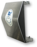
Heat Shield #14525
Naturally, manufacturers and fabricators have taken a number of measures over the years to combat heat exposure. While intense heat can certainly be irritating for the welder, the impact is more than an issue of comfort. There are significant safety, liability and productivity considerations as well. Reflective heat when welding is very hot. The reflective heat and weld puddle that is present when MIG welding aluminum is even hotter. The D/F Machine Specialties Heat Shield for the MIG Pistol gun directs the heat away from the hands, significantly reducing temperatures. Unlike other heat shields, the D/F heat shield has a dual wall design. The outside wall reflects the heat and provides and insulator from the inside wall. It also protects the hands and the torch from weld spatter. What’s more, the heat shield is comfortable and lightweight, so it can be mounted on a D/F Pistol gun without sacrificing performance. You won’t even notice the heat shield is there.
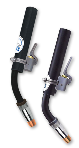
Air-Cooled Curved 35, 45 and 55 degree MIG Guns (7/16"-3/4" Gas Cup ID)
Drawings Accessories
Overview
The air-cooled CTA/CCA series curved MIG gun configurations come pre-assembled and ready to install. All models feature individual replaceable service connections. Optional cable/hose protector sheath is available.
Features
- 400 Amp CO2, 260 Amp Argon Current Capacity - 1/0 Power Cable
- Several Nozzle Body Configurations Available
- Heavy Duty Brass Inner Body
- Chrome Plated Brass Front End - Heavy Duty Copper Nozzle
- Standard and Quick-Disconnect Utilities Available
- High Temperature Insulation
Model Explanation
- CCA - Curved, Collet Action (Slip-In Tip), Air-Cooled
- CTA - Curved, Threaded Current Tip, Air-Cooled
Model Specifications
| MODEL | CURRENT CAPACITY |
WEIGHT (APPROX.) |
RECOMMENDED WIRE DIA. RANGE |
INSTRUCTION MANUAL |
|---|---|---|---|---|
| 35° CCA, CTA | 400 amps CO2, 260 Amps Argon |
2.2 lbs | .030"-.062" Hard/Cored, 3/64"-1/16" AL |
405 |
| 45° CCA, CTA | 400 amps CO2, 260 Amps Argon |
2.2 lbs | .030"-.062" Hard/Cored, 3/64"-1/16" AL |
462 |
| 55° CCA, CTA | 400 amps CO2, 260 Amps Argon |
2.2 lbs | .030"-.062" Hard/Cored, 3/64"-1/16" AL |
463 |
Barrel Dimensions
| MODEL | LENGTH | DIAMETER OF BARREL HOUSING | DIAMETER OF NOZZLE BODY | NOZZLE TO BODY TUBE CLEARANCE |
|---|---|---|---|---|
| 35° CCA, CTA | 14.375" | 1.450" | 1.0625" | 5.000" |
| 45° CCA, CTA | 13.75" | 1.450" | 1.0625" | 5.1875" |
| 55° CCA, CTA | 13.125" | 1.450" | 1.0625" | 5.375" |
Ordering Information
For Hard & Cored Wire
| DESCRIPTION | CODE NO. | ||
|---|---|---|---|
| 35 Degree Model CCA, CTA Series 400 1/0 Cable |
10 Ft. Casing |
12 Ft. Casing |
15 Ft. Casing |
| with Nozzle Body 13197 | 17849 | 17850 | 17851 |
| 45 Degree Model CCA, CTA Series 400 1/0 Cable |
10 Ft. Casing |
12 Ft. Casing |
15 Ft. Casing |
| with Nozzle Body 13197 | 19810 | 19812 | 19815 |
| 55 Degree Model CCA, CTA Series 400 1/0 Cable |
10 Ft. Casing |
12 Ft. Casing |
15 Ft. Casing |
| with Nozzle Body 13197 | 15570 | 15572 | 15574 |
Manuals & Downloads
Instruction Manuals
| TORCH MODELS | DOWNLOAD |
|---|---|
| 35° CCA, CTA | 405 |
| 45° CCA, CTA | 462 |
| 55° CCA, CTA | 463 |
Other Documents
| DESCRIPTION | DOWNLOAD |
|---|---|
| Torch Connection Options |
Utility Station #45184
The D/F Utility Station is required for all D/F torch installations. Typical modern torch setups utilize a unitized cable assembly with a power pin. D/F torches take an alternative approach to the setup. The torches use a separate gas hose, water-in hose, Water Out & Power Cable, and casing/conduit. When one cable goes bad it is simply replaced instead of attaching an entire new unitized cable assembly; a huge cost saver! This is also where the D/F Utility Station comes into play. For D/F Air-Cooled Torches, the gas hose and power cable are interfaced with the customer's existing lines via the Utility Station. The D/F torch leads plug into the front of the Utility Station. Into the back of the Utility Station go the customer's utilities. Read more on the D/F Utility Station product page.
For more information on proper use of the D/F Utility Station, and to see the various torch connection options, please download the Torch Connection Options one-sheet.