
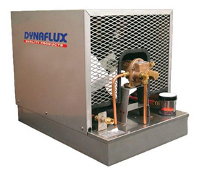
Dynaflux Water Chillers
MTA Water Chillers
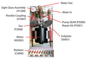
Drawings More Info
Overview
For jobs requiring high deposition, extended periods of arc time or multiple torches, D/F recommends that a quality water chiller be implemented in a water-cooled MIG & TIG welding operation. D/F Machine Specialties does not manufacture or sell chillers, we only recommend them. Cooling capacity and flow rate are crucial for proper cooling, and will prolong the life of the welding equipment, gas nozzle, and current tip. Very often we run into Miller Coolmates and Lincoln Electric Cool Arcs, and these units do not have the capacity for production environments when welding aluminum, using large diameter wires, in flux cored applications, ID bore welding, in pulse applications, making long welds, and with long duty cycles. A good chiller on a heavy duty water-cooled torch will reduce downtime and consumable costs.

The D/F torch is famous for the fact that if it is chilled properly (at least 15,000 BTU's and a 5 gallon reservoir), the welder can grab the front of the torch with their bare hand and it will be cold to the touch seconds after welding. With the proper chiller, this can be done even after a 4 hour arc time.
Up until recently the Bernard 6500SS (Weldcraft, ITW) was an industry standard. Unfortunately the Bernard 6500SS has been discontinued. It wasn't necessarily the best one out there, but it did meet the minimum requirements for most welding applications. The specs on the Bernard 6500SS have been included for reference. Cross-referencing the Bernard 6500SS with the Miller Coolmates and Lincoln Cool Arcs available today will show that the Lincoln Cool Arcs and Miller Coolmates are not adequate chillers. Once again, D/F Machine Specialties does not manufacture or sell chillers, we only recommend them. The industry has changed over the years. With heavy duty quality products being discontinued, and the “Big Box” companies pushing inadequate water circulators, lately we have been recommending the Dynaflux line of chillers. The Dynaflux R1200 is the minimum recommended chiller. If the job calls for wires larger than 1/16”, or for very long welds or high duty cycles, the R2000 is the preferred chiller. For very difficult jobs with extreme duty cycles the R4000 is recommended. The R4000 can also be used to chill 2 or more torches with the use of a manifold. For multiple torch, large cooling systems, MTA has many different sizes and options. It is very unfortunate that there are people using the Miller Coolmate 4's and the Lincoln Cool Arc 40's with D/F Machine Specialties torches. However, this is a testament to how robust in design the D/F torch is; our torches are so heavy duty that they still work in most applications, even with inadequate chillers. However, with these inadequate chillers there may be a decrease in weld quality, the torches may overheat and will not last as long, consumable life will certainly decrease, and other problems may occur.
Here is a link to the Dynaflux chillers – We do not sell chillers, we only recommend them to see our torch perform properly: Dynaflux Chillers
Included for reference are links to some of the more popular chillers used today.
- Bernard 6500SS – Minimum required specifications
- Lincoln Cool Arc 40 – Inadequate circulator, not a chiller, 2 gallon reservoir too small
- Lincoln Cool Arc 55 – Inadequate chiller (4,880 BTU/hr), 2.375 gallon reservoir too small
- Miller Coolmates – Inadequate chiller (6,070 BTU/hr), 3 gallon reservoir too small
*When comparing chiller specifications, please make sure to take note of the asterisks (*). Max specifications are based on a 25°C (77°F) factory environment at maximum flow with a 65°C (149°F) coolant temperature rise. Every factory that a D/F torch is welding in usually has environments near or above 100°F. As soon as you strike an arc, the front of the torch is at a minimum of 200°F or more.
The Bernard 6500SS had chilling capacity of 14,500 BTU/hr and a 6 gallon reservoir, the minimum required cooling specifications. The Lincoln Cool Arc 40 is not a chiller, it is a circulator, and the 2 gallon reservoir (1/3 of the minimum size capacity with NO cooling capabilities) is too small. A Lincoln Cool Arc 55 is also too small with very little cooling properties (4880 BTU/hr, 1/3 of the required minimum). A Miller Coolmate does at least have some cooling properties. However, the problem is that you can't look at the Coolmates’ max ratings, you have to look at the little asterisks by the ratings and read the minimum ratings (6,070 BTU/hr).
We all know that the conditions where these chillers and torches are have an ambient temperature of over 100 degrees before you strike an arc. The D/F Machine Specialties torch, when cooled properly, should always be around 55 degrees, even right after welding for 4 hours. D/F torches are manufactured so that if you hook them up to a common hose and a water faucet (30psi) that 1 gallon of water per minute will pass through a torch and its utilities (water in hose, and water out & power cable). Very often the chiller may be 25 ft away from the torches. It takes time and a lot of liquid to travel 25ft to the torch and back, a 2 gallon reservoir would be empty. Remember that the torch’s water out & power cable is not cooled until the coolant has gone through the torch and out the water out & power cable. If water is not flowing through the D/F torch for a least 1 minute prior to striking an arc, when you apply the power and water hits the “hot” water/out & power cable, you will generate steam. Steam can damage the torch's internals in seconds causing a leak, or it can also blow out the torches water/out & power cable. A flow switch can be installed after the return line ensuring that coolant is present at the return line prior to striking an arc. To do the demanding welding required of D/F torches you have to run a chiller that has an actual heat exchanger that does at least 15,000 BTU’s with a minimum of a 5 gallon reservoir. The torches will be cold to the touch seconds after welding. You will also see your nozzle life, tip life, and torch life increase. Copper, which is what contact tips and nozzles are made out of, will begin to break down around 300 degrees. These temperatures can be reached within seconds of striking an arc. It cannot be stressed enough how important it is to properly water-cool the torch to keep the tip and nozzle cool. Once a tip overheats, the wire will eat away at the tip causing the hole to become out of round. This will result in loss of conductivity, unstable arc, weld quality inconsistencies, and possibly a burnback. Do not forget that D/F’s new series of Automatic & Robotic Water-Cooled-to-the-Tip torches actually places the contact tip in the water-cooling. The colder you keep the torch, the colder the tip stays and the longer the tip will last, once again saving consumable cost and reducing downtime and maintenance.
Cooling a MIG or TIG torch can be compared to running an automobile with oil. If the car has too little oil, the parts will quickly break down and seize. If the oil is not changed regularly, the engine and lines can become clogged and deficient. Neither is good for the life of an engine. Similarly, if a torch is run with too little cooling fluid, it cannot maintain a cool enough temperature causing the torch to overheat, the contact tip to seize up on the wire, or the torch or power cable to burn up. If the fluid is not checked and changed, the equipment and lines can become clogged, resulting in deficient cooling of the gun. Neither is good for the life of the equipment.
Copper is a soft material but is required in the manufacture of contact tips and gas nozzles. Copper will begin to break down and get soft when it goes above 300 degrees. If you can control the temperature of the current tip and gas cup you can increase the life up to 14 times or more over an air-cooled torch, or up to 7 times or more over an insufficiently water-cooled MIG torch. Because D/F has water-cooled-to-the-tip torches which not only cool the inside but also the outside of the torch, the contact tip is recessed in the water cooling and the tip life is increased up to 7 times over other manufacturers’ torches. The same holds true for the gas cup or nozzle as it is also threaded up into the water cooling, resulting in nozzles lasting months instead of days.
When pulse welding or welding aluminum it is very critical to have a heavy duty water-cooled torch and chiller because of the heat involved. If the wire starts to seize up in the contact tip after a few feet of welding, the contact tip will be blamed for having too small of a hole, or the wire for being oversize. This very often is not the case. Failing to control the temperature of the contact tip with a proper chiller and a torch with water cooling on the tip will lead to the tip overheating and seizing up on the wire. Not only is the contact tip junk but you now have to rework the start and stop positions of the weld on the aluminum work piece.
In order to provide proper cooling and optimum equipment performance, a properly sized liquid chiller is essential. Download our chiller one-sheet to help select the proper chiller for your application.
Dynaflux Water Recirculators
For jobs requiring high deposition or extended periods of arc time, D/F recommends that a Dynaflux water recirculator Model R1200 or better for semi-automatic and hand gun applications, R2000 or better for automatic and robotic applications, and Model R4000 for ID Bore Torches be considered. Precise temperature control maintains the cooling at constant temperature, thus prolonging the life of the welding equipment and more specifically extending the service life of the gas nozzle and current tip.
Dynaflux has been a leading chemical manufacturer since 1972 and a supplier of high quality water recirculators for over thirty years. They are proud to offer products that are all made in the USA.
Dynaflux offers a broad range of chiller models for applications. D/F specifically recommends the 'R' series, built for reliability with rugged, durable construction that will provide years of trouble free operation and service.
Contact Dynaflux today to discuss your unique cooling application.
Phone: 800.334.4420
Fax: 770.382.9034
Standard Features
- Up to 55,000 BTU
- Up to 10 gallons per minute at 50 psi
- Adjustable up to 100 psi
- Visible water level through tank or sight glass
- Thermal overload detection
Please Note: D/F does not sell this item, we only recommend them. Please visit Dynaflux's web site for specifications and ordering information regarding Dynaflux Water Recirculators.
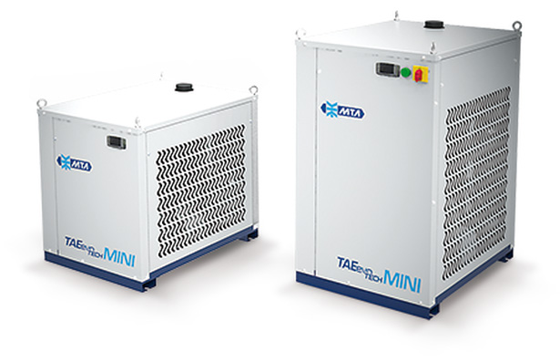
MTA Chillers
For jobs requiring high deposition or extended periods of arc time, D/F recommends that a MTA liquid chiller be considered. Precise temperature control maintains the cooling at constant temperature, thus prolonging the life of the welding equipment and more specifically extending the service life of the gas nozzle and current tip.
MTA is a global manufacturer and provider chiller solutions. Known and recognized for years of experience in the cooling industry, MTA provides high reliability, compact dimensions and high efficiency chiller solutions for your industries and applications. Easily serviceable machines provide optimal up-time and peace-of-mind, knowing your application is running with optimal cooling.
Contact them today to discuss your unique cooling application.
Phone: 716-693-8651
Fax: 716-693-8654
Manuals & Downloads
Other Documents
| DESCRIPTION | DOWNLOAD |
|---|---|
| Chiller Specifications: Choosing the Proper Chiller for Your Application |
Fluid Flow Switches
Fluid Flow Switches are designed to monitor the flow of fluid through a line. They are designed to prevent catastrophic torch and parts failure in the event of low coolant flow. They are frequently used to assure that water is flowing in a cooling circuit, however they may be used in a wide variety of applications with many different fluids. Whether monitoring coolant flow to weld guns or to the whole coolant circuit for a weld cell, the flow switch quickly and reliably detects the loss of flow continuity created by a cap loss, hose burst and other similar events.
The safety flow switch monitors cooling fluids or other liquid flows, and is designed to trip an internal relay if the flow rate drops below an adjustable trip point. This switch may be used to shut down equipment or sound an alarm before damage is done to the equipment. A switch may be used as "Normally Open" or "Normally Closed". This switch requires 115v input and has a 24v relay contact cable.
The copper electrode (contact tip or current tip) carries the power and generates the arc, and is closest to the heat source, so it requires direct cooling. The gas cup or nozzle is also right down in the heat. D/F Machine Specialties is one of the few torch manufactures that not only has the copper gas cup threaded into a copper nozzle (not brass) that is water-cooled, but the contact tip is also threaded into copper threads (not brass) that also water-cooled hence the name Water-Cooled-to-the-Tip. This water cooling provides a high flow velocity of coolant over the interior rear surface of the electrode (contact tip) and gas cup (gas nozzle).
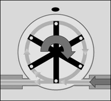 How Do Fluid Flow Switches Work?
A flow switch placed inline of the return water line will detect the proper flow of water through a torch. When liquid flows through the sensor body of the flow switch it spins a rotor. Magnets in the rotor create a voltage in an induction coil mounted in the sensor body. The amplitude of the induced voltage is at a maximum when the magnet is immediately adjacent to the coil. The amplitude of the induced voltage is proportional to the rotational velocity of the rotor and the linear velocity of the liquid as it passes through the sensor body. This amplitude of the induced voltage is measured by a simple electronic circuit that compares it to a user-set trip point voltage.
Many flow switches commonly work on a relay interface. When the induced voltage is greater than the voltage achieved at a user-selelected trip point flow rate, the relay is energized. If the induced voltage is less than the voltage achieved at the user-selected trip point flow rate or if the fluid stops flowing, power to the relay is shut off, and the relay is de-energized. The de-energized state is called the relay's normal position. The change of state of the relay is interpreted by the user’s equipment to control other system functions.
Another common interface is a transistor interface. When the induced voltage is greater than the voltage achieved at a user-selected trip point flow rate, a transistor is turned ON. If the induced voltage is less than the voltage achieved at the user-selected trip point flow rate, of if the fluid stops flowing, a transistor will turn OFF. The change is state of the transistor is interpreted by a user-supplied interface to control other system functions.
Threaded Connections
Pipe threads seal by making metal-to-metal or plastic-to-plastic contact between male and female components. Consequently they are particularly prone to the damaging effects of galling, which occurs when two surfaces move against each other under pressure. When installing pipe threads it is essential to use a high quality lubricating and sealing material. WARNING: Do NOT use anaerobic pipe sealants such as LOCTITE or SWAK brand sealants with these sensors. The aggressive chemical nature of these materials will cause cracking of polysulfone faceplates. Use Teflon tape or a PTFE-based liquid sealant to provide lubrication for the junction and a leak-tight connection at both input and output connections. Real-Tuff and Hercules are two of many suitable brands of PTFE-based sealants. Do not over-tighten the connection. Refer to instructions for installation of the mating fittings for information on torque requirements. Leak testing of all connections in your flow circuit is recommended. Pressurizing the system with air and external testing with a dilute soap solution can help identify leaking connections.
Filtering
Your circulating fluid may contain particles. While not essential to the operation of the flow sensor, it is good practice to filter your fluid. A 100-micron filter is often used to remove rust and other particles from the fluid. This can increase the lifetime of pumps and other fluid system components as well as reducing wear in the sensor.
Fluid Temperature Range
Flow sensors with plastic bodies should not be used above 75°C. Metal bodies with metal faceplates may be used with liquids at higher temperatures, but ideally should not exceed 110°C.
Maintenance
Maintenance of the sensor is normally limited to cleaning the chamber in which the rotor spins and annual recalibration. The frequency of cleaning will vary with the type of fluid being run and the cleanliness of that fluid. In most cases, annual cleaning immediately prior to recalibration is sufficient.
The Effect of Poor Water Flow
When water-cooled torches do not receive a high enough flow of water, the tips and nozzles or gas cups remain hotter and will not perform correctly. The result is accelerated deterioration of the welding surfaces, which is caused by putting heat in faster than it can be removed. If you were to line up 3 identical electrodes, one on an air-cooled torch, one on a water-cooled torch, and one on a water-cooled-to-the-tip torch, with all other factors the same, a significant difference in the effects of heat on the contact tip would be apparent. The air-cooled torch contact tips and nozzles would have the greatest amount of welding surface deterioration, which is why air-cooled torches use on average 14 times as many contact tips and nozzles, which demonstrates what a major difference a small amount of change in water flow can cause. The copper should be comfortable to the touch or it is too hot. Copper is rated at its full conductivity at 68 degrees Fahrenheit. Class 2 copper is 85 percent conductive at 68 degrees F. When copper turns dark, it has gotten too hot and oxidized. When it oxidizes it loses its ability to conduct electricity.
Preventative Maintenance
Water-Cooled Welding Cable (Water Out & Power Cable)
Check the following as prescribed:
- Are the cable sleeve or cable ends warm to the touch? If so, and water elsewhere in the circuit appears to be flowing, the cable is plugged. This is usually caused by broken wire strands. This plug is difficult to clear, so the cable should be replaced.
- Does the cable jacket leak? If the cable has gotten too hot, water may leak out of the ends. The cable jacket can be replaced by the manufacturer if needed.
Other Cables (Water In Hose, Gas Hose)
A preventive maintenance program can be instituted for checking cables and forecasting life that includes:
- A micro-ohm quality check for resistance of cables as .they come in to ensure they meet the manufacturer's specifications.
- On-line periodic checks of cables and welding parameters (such as welding current).
- A monthly check of machine cables. The frequency of checks can be decreased based on data collected. When cable resistance doubles, it is time to change the cable.
Torch coolant is a mixture of de-ionized water and ethylene or propylene glycol to depress the freezing point. Many shops use plain de-ionized water if there is no risk of freezing. Ethylene or propylene glycol is the same agent used in automotive cooling systems. However, never use automotive antifreeze in a plasma system. Most commercial antifreeze has material in it to clog small leaks. This makes it unsuitable for use in a plasma torch.
Filters
Most systems use a particulate filter to remove contamination from the torch coolant. These filters are similar to commercially available water-treatment filters, usually a 5-micron paper filter or de-ionizing filter.
Heat Exchangers
Heat exchangers for plasma cooling systems usually consist of a radiator and fan combination. Fans direct airflow through the radiator to remove heat from the torch coolant. Some systems use a refrigerated chiller to cool the torch coolant.
Coolant Reservoirs
Check the coolant reservoir daily and top it off as necessary to make sure the coolant supply always is adequate. If coolant levels are too low, air may be introduced into the coolant stream, which reduces cooling. If the system is interlocked, low coolant may cause intermittent or total shutdown. If the system is not interlocked, air may cause the pump to overheat and fail. Coolant reservoirs usually have level indicators, float switches, and temperature switches installed in the tank to prevent overheating.
System Troubleshooting
The individual components in the plasma cooling system all are designed to ensure one thing: an adequate volumetric flow rate to the torch for cooling.
Flow typically is measured in gallons per minute (GPM) or liters per minute (LPM). Each torch has a specific flow requirement in the specifications section of the operator's manual. Typical flow rates are 1 to 1.5 GPM.
The following is a five-step approach for verifying proper coolant flow and troubleshooting flow problems. Before performing maintenance and troubleshooting on a plasma system, always read your operator's manual and understand all safety precautions.
- Remove torch parts. When troubleshooting, begin at the torch. Remove the consumables and inspect them for signs of overheating, contamination, or damage.
- Turn on coolant pump. You may need an assistant to keep the pump running during flow measurement and to top off the coolant level if it gets low. Coolant should flow directly out of the center of the cooling tube in the torch.
- Measure coolant supply flow to torch. Use a bucket to catch coolant that is discharged from the cooling tube. Collect coolant over a time interval of 60 seconds and then shut off the pump. Measure the volume of coolant in gallons or liters. The D/F torches should have a minimum of a ½ gallon per minute ideally a minumum of 1 gallon per minute. Convert this volume to a flow rate by dividing gallons collected by the time interval (60 seconds) to attain GPM or LPM. Compare this measurement to the specified flow rate in the operator's manual. The flow in an unrestricted torch (without parts in it) should exceed the manufacturer's specification. If it doesn't, check to see if:
- The pump pressure is too low. If it is, adjust the pump setting.
- The screen filter in the pump is restricted. Clean it if necessary.
- The torch or its supply line is restricted. Blow debris out with compressed air or replace if needed.
- Reassemble the torch. Using clean new parts, reassemble the torch. Parts must be in place for a proper flow check to ensure there is no leaking and water is flowing thought the torch body and the water-cooled nozzle assembly.
- Measure the coolant return flow from the torch. Measure the coolant flow rate at the return to the coolant reservoir. Disconnect the plastic hose from the coolant tank. Again, use a bucket and an assistant to collect water for a 30-second interval then shut off the pump. Convert the measurement to GPM. Compare this flow rate to the manufacturer's specification. If the GPM doesn't exceed the manufacturer's specification, check to see if:
- The pump pressure is too low. If it is, adjust pump setting.
- The return coolant line or torch is restricted. If so, blow debris out with compressed air or replace it.
- The radiator is plugged. Use a high-pressure washer to clean it or replace it if necessary.
- The paper filter is restricted. Replace it or remove it temporarily for troubleshooting if necessary.
- A liquid flowmeter is an alternative to the bucket test commonly used to measure coolant flow to and from the plasma cutting torch.
- An alternative to the bucket test is to purchase an inexpensive flow meter designed for liquid flow measurement in the range of 0 to 2 GPM. This device can be installed permanently in the return side of the system at the reservoir. It is a suitable visual tool for maintaining the plasma system and cheap insurance against a costly breakdown.
Cooling MIG & TIG Torches
The Importance of Cooling MIG and TIG Torches
Every water-cooled MIG system uses some sort of fluid to cool the torch, and to prevent the electrode and nozzle from melting due to the high temperature of the arc and the heat generated from welding. As the current gets higher, a separate cooling liquid is required to carry away all of the heat.
One might think the biggest source of heat in the system would be the MIG torch, but it's usually the power leads. The power leads consist of a flexible braided metal cable inside of the cooling hoses that connect to the torch body. Because those cables conduct a large amount of electrical current in a relatively small cross-section, they generate a lot of heat that has to be removed to prevent the hoses from melting.
Inside the torch body, the electrode is a big heat source. The arc attaches to the face of the electrode, so a lot of power is passing through a small metal part. To keep it from melting, cooling fluid circulates against the back side of the electrode.
After cooling the torch, the coolant is slightly warmer than it was when it entered the torch. Coolant that is pumped around and around in a closed circuit will keep getting warmer and warmer until it can no longer cool the torch. To keep the coolant temperature low, it is pumped through either a cooler or a chiller.
A “cooler” is typically made up of a simple radiator with a fan blowing air through it. As the coolant flows through the radiator, heat is conducted out of the liquid and into the metal radiator. The heat is then conducted into the moving air and carried away. A “chiller” refers to a system that uses a refrigerant, a compressor, and a heat exchanger to dramatically reduce the temperature of the coolant. Whether using a cooler or a chiller, the torch coolant is the same.
In either case, the coolant is pumped from a reservoir at relatively high pressure so that sufficient flow rate can be maintained through the small passageways inside the torch, and even through long hoses. Insufficient coolant flow will allow the torch overheat.
How a MIG Torch is Cooled
Inside the MIG torch, the first thing the coolant hits is the back of the electrode. The opening for coolant to flow against the back of the electrode is very thin so that it moves through at high speed and carries away heat more efficiently. This is the tightest spot in the torch, and is the point at which there is the biggest pressure drop in the coolant system.
After cooling the electrode, the liquid circulates back up into the torch body and then out through a different passageway so that it can cool the nozzle. Swirling coolant around the outside of the nozzle helps extend the life of the nozzle. The coolant then exits the torch and returns to the cooler.
What Types of Coolant are Available?
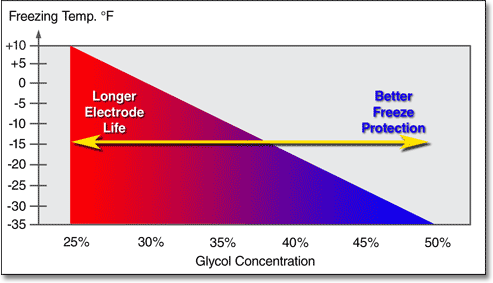
There are a number of different types of MIG torch coolant available, from many different manufacturers. Most equipment manufacturers offer their own brand of coolant, and there are also several after-market brands. They all use either ethylene glycol or propylene glycol mixed with distilled water as the main ingredients. Most mixtures range from 25 to 50% glycol (75 to 50% water), although there is at least one coolant that has no glycol at all. They offer freeze protection to anywhere from +12º F to as low as -35 F.
The glycol additives reduce the freezing temperature. The higher the glycol content, the lower the freezing temperature. But the glycol additive also has an adverse effect, it reduces cooling efficiency, which shortens consumable life.
![]() Caution: Plasma Torch Coolant is Clear! Some torch coolants contain dyes. These coolants may work fine in TIG or MIG torches. However, these should never be used in a CNC plasma cutting machine, where the temperature and voltage is much higher. Colored coolant has known to solidify, creating a jelly-like substance that will clog your torch and water cooler.
Caution: Plasma Torch Coolant is Clear! Some torch coolants contain dyes. These coolants may work fine in TIG or MIG torches. However, these should never be used in a CNC plasma cutting machine, where the temperature and voltage is much higher. Colored coolant has known to solidify, creating a jelly-like substance that will clog your torch and water cooler.
Some coolant mixes will have other trace ingredients, which may or may not adversely affect your welding system. These could be included as a preservative, or to prevent algae or bacterial growth. Sometimes a coolant may be manufactured to loose specification tolerance. For example, the bottle of coolant may say 30% glycol, but the specification by which it was manufactured might have been 30% +/- 10%. If the actual chemical supplier had sub-standard quality control, the resulting mix that you get might be significantly outside of that range.
Which is the Best Coolant Mix to Use?
So which is the best one to use? The answer depends primarily on the working environment in your shop. Here is what you need to know:
Pure water or DI water is the best coolant! That’s right, when it comes to conducting heat away from the electrode and discharging it through a radiator, pure water does the best job. And the better you cool the electrode, the longer it will last. The coolant mix can have a huge impact on consumable life. Changing from a high percentage to a low percentage of glycol in the coolant can increase consumable life by 30% or more!
It is true that antifreeze can reduce system performance somewhat. However, under near-freezing conditions, system performance can actually be improved with the use of antifreeze. If your chilled-water supply temperature is 50 degrees F (10 degrees C), it is likely that you will need antifreeze. It is likely that flash freezing of the plates in the evaporator will rob system efficiency, or, worse yet, causing permanent damage to the heat exchanger itself.
It is important that the correct amount of coolant be used so that reductions are as low as possible while the system gains optimal benefits from it. Antifreeze used in proper concentrations will keep flash freezing from occurring and reduce the possibility of chiller failure.
What to Use & What not to Use
Never use automotive anti-freeze in a chiller system. The additives found in this type of antifreeze can foul heat exchangers and result in poor heat transfer. The two antifreeze types to be considered are propylene glycol and ethylene glycol.
The two antifreeze types to be considered are propylene glycol and ethylene glycol. They are available in temperature ranges of -60 degrees to 350 degrees F (-51 degrees to 177 degrees C) and work well for chiller applications. With glycol in the system, chilled water is protected from freezing in the heat exchanger.
Ethylene glycol tends to be the preferred coolant in most chiller applications. However, if your application is pharmaceutical, or if contact with food or potable water is possible, a clear propylene glycol is the right choice. Coolant solutions with dyes or special inhibitors are toxic and should not be used in these applications. Some states and local regulations do not accept ethylene glycol and require the use of propylene.
System construction needs to be considered when choosing the type of antifreeze. Some manufacturers offer inhibited glycol which can also help reduce corrosion. Even with inhibited glycol, chilled-water systems using iron, steel, or galvanized water piping and fittings can suffer from corrosion problems and pitting.
Despite long-standing industry knowledge of their potential for problems, these metals are still encountered in system applications, both retrofits and some newer systems. Chiller systems should use copper, stainless, or Schedule 80 PVC pipe and fittings.
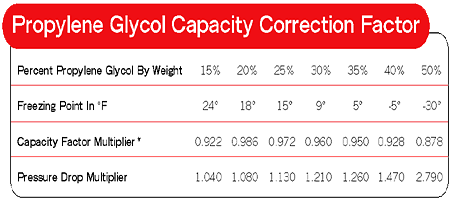
Table 1. At standard ARI 590 condition: 54 degrees F entering fluid temperature, 44 degrees leaving fluid temperature, 95 degrees ambient temperature, 0.0005 fouling.
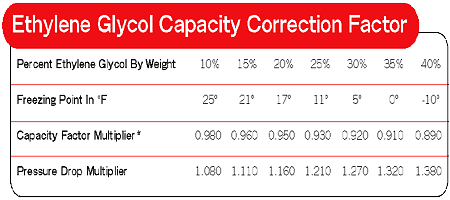
Table 2. At standard ARI 590 condition: 54 degrees F entering fluid temperature, 44 degrees leaving fluid temperature, 95 degrees ambient temperature, 0.0005 fouling.
Antifreeze Effects
As was mentioned earlier, antifreeze will reduce chiller system performance to a degree, depending on the amount introduced. The more antifreeze that is added, the lower the efficiency.
BTU output is reduced as the concentration of glycol is increased. In most cases, it is not recommended to use concentrations of propylene glycol higher than 50 percent by weight, or concentrations of ethylene glycol higher than 40 percent by weight.
For new systems, system design engineers will compute how much antifreeze you should use. (See Tables 1 and 2 for propylene and ethylene glycol capacity correction factors.) When calculating the required chiller size for your application, the output of the chiller should be corrected to reflect the effect of the lower heat transfer properties of glycol vs. water. Pump flow rates also decrease as glycol concentrations are in-creased. The system’s total pressure drop should be corrected for the increase of glycol and the process pumps sized accordingly.
For retrofits, use the conversion factor, but work it backwards from the way it would be applied for new systems. Figure the loss of cooling efficiency.
Reviewing the chiller settings, validate the process heat load or cooling requirements and change the process to accommodate the reduced cooling.
Water quality and system design efficiency also determine “the limiting or safe low-temperature freeze point.” Some chillers may go as low as 47 degrees F (8 degrees C), while older or less efficient models may require settings as high as 60 degrees F (16 degrees C) to keep water from freezing.
Once a system is protected with coolants, it is important to keep it that way. It is a good idea to keep a premixed antifreeze solution on hand in five-gallon buckets or drums for use in the event of occasional system water loss. For example, if you determine you need a 20 percent glycol solution, and you have leaks, spills, or evaporation, you could lose water. These losses can effectively change your antifreeze solution concentration. If maintenance has that five-gallon bucket on hand, it’s right there for the technician to add if the system needs it. There is no guessing on how much antifreeze is required. Utilizing the premixed solution will allow maintenance of the correct limiting or safe low-temperature freeze point.
It stands to reason that a chiller system’s antifreeze should be checked periodically. The frequecy entirely depends on the system. Residential systmes, for instance, might have relatively low water loss; process systems in some other environments might require more frequent checking. Go with the manufacturer’s recommendations for regular maintance and service.