D/F MIG (GMAW) & TIG (GTAW) torches can hook up to any of the different Miller, Lincoln, Esab, Welding Alloys, Fronius, Tweco, etc., power sources and wire feeders. Every wire feeder manufacturer has different sized holes where the torch’s conduit or casing plugs into the wire feeder. These pins are called power pins. Since our competition uses unitized lines or leads (gas, water, power, and conduit in 1 cable), they put the power on the torch at the drive rolls. A unitized cable is not only more expensive, but it is harder to work on. It is restricted in size by small passages for water, gas and wire. If a composite cable assembly wears out or is damaged, the whole assembly must be replaced. They also cannot support a large enough size inner power cable to bring the necessary power to the torch. The water-cooling and gas coverage are both limited by the size restrictions.
D/F takes an alternative approach to the setup. We do not refer to the pins as power pins, we call them feeder adapters. We do not put the power on the pin or the feeder adapter. We put the power (4/0 Cable) into the back of our utility station. The torches use a separate gas hose, water-in hose, Water Out & Power Cable, and casing/conduit. When one cable goes bad it is simply replaced instead of attaching an entire new unitized cable assembly; a huge cost saver! This is also where the D/F Utility Station comes into play. The gas hose, water-in hose, and Water Out & Power Cable are interfaced with the customer's existing lines via the Utility Station. The D/F torch leads plug into the front of the Utility Station. Into the back of the Utility Station go the customer's utilities. The back includes industry standard 3/8" shanks to allow the customer to connect the water in and water out lines, and a 3/16" shank to connect the gas line. Along with these hoses, the customer must plug the a 4/0 power cable directly from the power source to the back of the Utility Station. This is how the D/F torches are powered, NOT with a power cable to the wire feeder; there can be no jumper cable from the drive roll to the Utility Station. The power must travel through the Utility Station and down to the torch via the Water Out & Power Cable, hence the name. The power travels from the utility station down our 650 amp water/out & power cable to the torch body where the power is put on the tip that is recessed into the front of our water cooled inner body. It is most important to remove the 4/0 power cable from the lug of the wire feeder drive roll stand, strip the cable back roughly 2", and insert the 4/0 power cable into the back of the D/F Utility Station. Finally, a short gas hose jumper is needed for control of the gas. Remove the small black 3/16" hose that connects from the solenoid to the feeder input inside the wire feeder. The jumper can be attached by removing the 3/16" hose from the solenoid, and attaching the 3/16" gas jumper hose to the solenoid and to the back of the D/F Utility Station's 3/16" shank.
Not only are D/F torches water-cooled on the inside of the body, the nozzle is also water-cooled. The water cooled nozzle (the front of the D/F torch) is insulated from the body that is carrying the current. If a torch is properly mounted on the insulated body and not touching metal, you can actually grab the front of the torch because it is not hot. Since the water-cooled nozzle is insulated from the hot body, and because of the superior water cooling, the front nozzle will also be cool to the touch after welding at high amperage and preheat. This installation allows everything to run cooler and last longer.
Due to the fact that every welding application is different because of size restrictions, access restrictions, positioning restrictions, etc., D/F manufactures barrels in two variations, remote mount and direct mount. To directly connect a D/F torch to the wire feeder, simply thread the correct feeder adapter for the wire feeder into the top of the D/F torch and plug the torch into the wire feeder. The utilities leave the torch at a 90 degree angle and can be connected to the utility station.
Remote connection of a D/F torch requires a mounting bracket or robotic mounting arm to grab the torch. This arm or bracket is then mounted on a robot, fixture, gantry, x- y- z axis, or above a positioner or manipulator. The wire is brought into the torch through a conduit/casing (usually from 4ft-15ft). Remote mounting enables customers to get the wire feeder away from the pre-heat, torch heat, and the work. It also allows the end user to access hard to reach areas. Furthermore, it allows for all of the utilities to be protected together inside a fire resistant sheath.
A third mounting variation exists that somewhat combines direct and remote mounting and includes the utility station. A direct mount torch can be remotely mounted. We make this possible by putting an adapter on the top of the direct mount torch. This adapter will allow you to now attach a casing/conduit on the top of the torch and get the torch anywhere from 1-15 feet away from the heat. This method of remotely mounting a direct mount torch is preferred in installations where there is limited room for mounting and running the lines. This allows for easy access to the casing/conduit to be changed out, and for ease in changing liners. This method is used in hard banding applications by mounting a “dog bone” on the front of the water-cooled nozzle of the torch, and off of that mount will come the cold wire feed or sub arc attachments.
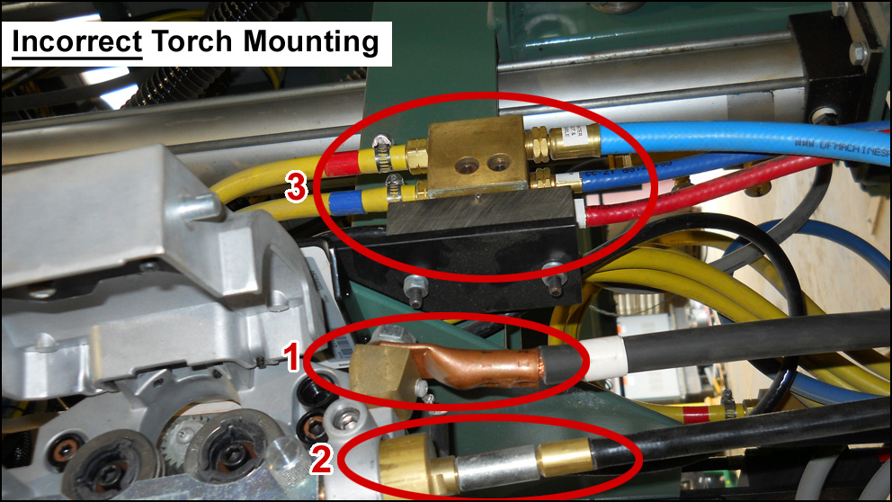
D/F torches must not be connected incorrectly (above). The power (1) cannot be placed on the wire feeder or drive roll stand, otherwise (2) the casing/conduit will be "hot" and you will burn the casing/conduit off the torch. If you are lucky enough to not burn it off the torch completely, you will be preheating the wire causing many other feeding issues and resistance heating issues. Instead the 4/0 power cable must be put into the back of the D/F Utility Station (3) so that the power can travel down the 650 amp water/out & power cable.
Examples of the two main correct mounting methods, direct and remote, and the third optional corect method are listed below:
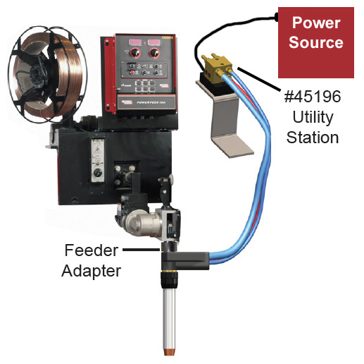
Direct Mount Torches
The torch is directly connected to (plugged into) the wire feeder.
To directly connect a D/F torch to the wire feeder, simply thread the correct feeder adapter (Miller, Lincoln, ESAB) for the wire feeder into the top of the D/F torch and plug the torch directly into the wire feeder. The utilities leave the torch at a 90 degree angle, clearing the wire feeder, and can be connected to the utility station. As you can see in the illustration, the 4/0 power cable goes directly from the power source to the D/F Utility Station (part #45196).
Direct Mount Water-Cooled-to-the-Tip Torches
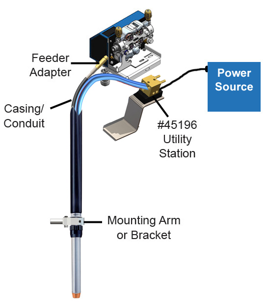
Remote Mount Torches
The torch is mounted away from the wire feeder and requires a casing or conduit to run wire to the torch.
Remote mounting of a D/F torch requires a mounting bracket or robotic mounting arm to grab the torch. This arm or bracket is then mounted on a robot, fixture, gantry, x- y- z axis, or above a positioner or manipulator. The wire is brought into the torch through a conduit/casing (usually from 4ft-15ft). Remote mounting enables customers to get the wire feeder away from the pre-heat, torch heat, and the work. It also allows the end user to access hard to reach areas. Furthermore, it allows for all of the utilities to be protected together inside a fire resistant sheath.
The power cannot be placed on the wire feeder or drive roll stand, otherwise the casing/conduit will be "hot" and you will burn the casing/conduit off the torch. As you can see in the illustration, the 4/0 power cable goes directly from the power source to the D/F Utility Station (part #45196).
Remote Mount Water-Cooled-to-the-Tip Torches
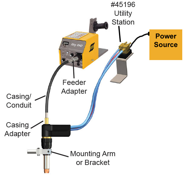
Remotely Mounted Direct Mount Torches
Remotely mount a direct mount torch.
The Direct Mount torch, instead of being directly plugged into the wire feeder, is mounted away from the wire feeder, and requires a casing adapter to receive the conduit to run wire to the torch. This unique solution might work for jobs with very limited space. This is the preferred method when using external feeds such as adding carbide to the weld.
The power cannot be placed on the wire feeder or drive roll stand, otherwise the casing/conduit will be "hot" and you will burn the casing/conduit off the torch. As you can see in the illustration, the 4/0 power cable goes directly from the power source to the D/F Utility Station (part #45196).