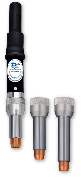
Standard Barrels
(7/16"-3/4" Gas Cup ID)
Drawings Accessories
Overview
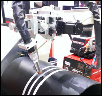 The models NCM/HTM remote mounted MIG torches have similar features designed to function efficiently on various applications and use threaded tips or slip-in tips respectively. These models are remote mount torches and have standard size gas nozzles (7/16" to 3/4" ID) for hard wire, cored wire and aluminum wire applications. Throughout the years, Pandjiris has used D/F Machine Specialties MIG and TIG torches exclusively. The typical Pandjiris cell would include these D/F torches mounted on manipulators, side beams, slides, and positioners.
The D/F torch is famous for the fact, that if it is chilled properly, the welder can grab the chrome front water-cooled barrel (not the copper gas nozzle/cup) of the torch with their bare hand and it will be cold to the touch seconds after welding. With the proper chiller, this can be done even after a 4 hour arc time. Make certain the cooling water supply is at least the minimum flow rate of 1 gallon per minute (for each inner body), at 40 psi (80 psi maximum) with a 6 gallon reservoir and a recommended 30,000 BTU/hr cooling capacity. Gun ratings are affected by shielding gas used, arc time, cooling time and inlet water temperature. Water outlet temperature should not exceed 27°C (80°F). The torch’s water out & power cable is not cooled until the coolant has gone through the torch and out the water out & power cable. If water is not flowing through the D/F torch for at least 1 minute prior to striking an arc, when you apply the power and water hits the “hot” water/out & power cable, you will generate steam. Steam can damage the torches internals in seconds causing a leak. It can also blow out the torches water/out & power cable. A flow switch can be installed after the return line ensuring that coolant is present at the return line prior to striking an arc. When High-Deposition GMAW, high current density, high amperages, preheat, or extended periods of arc time are used, a refrigerated liquid chiller with a larger reservoir is required. Precise temperature control maintains the cooling at a constant 13°C (55°F) temperature, thus prolonging the life of the welding equipment and more specifically extending the service life of the gas nozzle and current tip. D/F Machine Specialties does not manufacture or sell chillers, we only recommend them. Click here to see our recommended chillers.
Each D/F Machine Specialties welding gun is fully assembled and ready to install. In order to make the installation complete, the code number, wire size, wire feeder make/model (Lincoln wire feeders, Miller wire feeders, Tweco wire feeders, ESAB wire feeders, & EURO Quick Disconnect wire feeders), and inlet (as needed) must be specified when ordering. If special welding tools or accessories other than those listed previously are required, please consult with the factory. Get the right feeder adapter connection to fit your MIG wire feeder.
Features
- Water-Cooled Inner Body & Nozzle
- Small Frontal Area for Hard-to-Reach Locations
- Nozzle Length Extended by Applying One of Three (3) Different-Length Water-Cooled Nozzle Assemblies
Model Explanation
- NCM - Normal Duty, Collet Action (Slip-in Tip), Machine Barrel
- HTM - Heavy Duty, Threaded Tip, Machine Barrel
Model Specifications
| MODEL | CURRENT CAPACITY |
WEIGHT (APPROX.) | COOLING REQUIRED | RECOMMENDED WIRE DIA. RANGE |
INSTRUCTION MANUAL |
|---|---|---|---|---|---|
| NCM | 400 amps | 2.5 lbs | 3 quarts/min | .035"-3/32", 3/64"-3/32" AL |
551WM |
| HTM | 500 amps | 2.5 lbs | 3 quarts/min | .035"-3/32", 3/64"-3/32" AL |
Barrel Dimensions
| MODEL | LENGTH W/ 3" NOZZLE | LENGTH W/ 4" NOZZLE | LENGTH W/ 5" NOZZLE | DIAMETER OF W/C NOZZLE | DIAMETER OF BODY HOUSING |
|---|---|---|---|---|---|
| NCM, HTM | 9.25" | 10.25" | 11.25" | 1.125" | 1.625" |
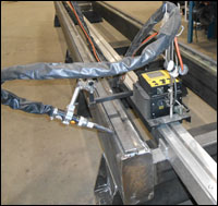
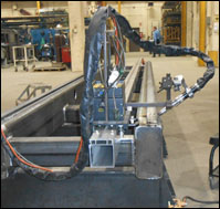
The Bug-O Modular Drive System is a single machine capable of connecting to any automated system and utilizes a convenient rail carriage track for many applications. The MDS allows you to produce precise, accurate cuts and welds. The Master Drive Unit features a high torque, precise motor for repeatable weld and cut patterns. Click here to visit Bug-O's website for more information about the Modular Drive System.
Ordering Information
Complete Barrel Only
| DESCRIPTION | CODE NO. |
|---|---|
| Model NCM (Slip-in Tip) | Code No. |
| Short 3" W/C Nozzle | 17439 |
| Inter. 4" W/C Nozzle | 17440 |
| Long 5" W/C Nozzle | 17441 |
| Model HTM (Threaded Tip) | Code No. |
| Short 3" W/C Nozzle | 17442 |
| Inter. 4" W/C Nozzle | 17443 |
| Long 5" W/C Nozzle | 17444 |
Complete Assemblies
| DESCRIPTION | CODE NO. | ||||||||
|---|---|---|---|---|---|---|---|---|---|
| Model NCM (Slip-in Tip) | 3 Ft. | 4 Ft. | 5 Ft. | 6 Ft. | 7 Ft. | 8 Ft. | 10 Ft. | 12 Ft. | 15 Ft. |
| Short 3" W/C Nozzle | 11731 | 11741 | 11747 | 11737 | 11774 | 11764 | 11703 | 11709 | 11715 |
| Inter. 4" W/C Nozzle | 11732 | 11742 | 11748 | 11738 | 11775 | 11765 | 11704 | 11710 | 11716 |
| Long 5" W/C Nozzle | 11733 | 11743 | 11749 | 11739 | 11776 | 11766 | 11705 | 11711 | 11717 |
| Model HTM (Threaded Tip) | 3 Ft. | 4 Ft. | 5 Ft. | 6 Ft. | 7 Ft. | 8 Ft. | 10 Ft. | 12 Ft. | 15 Ft. |
| Short 3" W/C Nozzle | 11734 | 11744 | 11754 | 11757 | 11777 | 11767 | 11706 | 11712 | 11718 |
| Inter. 4" W/C Nozzle | 11735 | 11745 | 11755 | 11758 | 11778 | 11768 | 11707 | 11713 | 11719 |
| Long 5" W/C Nozzle | 11736 | 11746 | 11756 | 11759 | 11779 | 11769 | 11708 | 11714 | 11720 |
Manuals & Downloads
Instruction Manuals
| TORCH MODELS | DOWNLOAD |
|---|---|
| NCM, HTM | 551WM |
| NCM, HTM (EURO Connector) |
590WM |
CAD Files & Drawings
| TORCH MODELS | CODE NO. | CAD FILE | PDF DRAWING |
|---|---|---|---|
| NCM 3" | 17439 | 17439 | 17439 |
| HTM 3" | 17442 | 17442 | 17442 |
| NCM 4" | 17440 | 17440 | 17440 |
| HTM 4" | 17443 | 17443 | 17443 |
| NCM 5" | 17441 | 17441 | 17441 |
| HTM 5" | 17444 | 17444 | 17444 |
| Note: CAD Models are the same for different length utilties Example: 17439 (3Ft. NCM 3") represents the same model as the 11764 (8Ft. NCM 3") | |||
Other Documents
| DESCRIPTION | DOWNLOAD |
|---|---|
| Torch Connection Options | |
| W/C Remote Mount MIG Torches One-Sheet |
Utility Station #45196
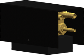
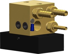
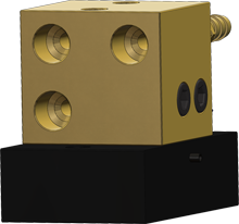 The D/F Utility Station is required for all D/F torch installations. Typical modern torch setups utilize a unitized cable assembly with a power pin. D/F torches take an alternative approach to the setup. The torches use a separate gas hose, water-in hose, Water Out & Power Cable, and casing/conduit. When one cable goes bad it is simply replaced instead of attaching an entire new unitized cable assembly; a huge cost saver! This is also where the D/F Utility Station comes into play. The gas hose, water-in hose, and Water Out & Power Cable are interfaced with the customer's existing lines via the Utility Station. The D/F torch leads plug into the front (see right) of the Utility Station. Into the back (see below) of the Utility Station go the customer's utilities. Read more on the D/F Utility Station product page.
For more information on proper use of the D/F Utility Station, and to see the various torch connection options, please download the Torch Connection Options one-sheet.

Series A High Capacity Barrels
(11/16"-1" Gas Cup ID)
Drawings Accessories
Overview
The models NCM-A/HTM-A remote mounted MIG torches have similar features designed to function efficiently on various applications and use threaded tips or slip-in tips respectively. These models are remote mount torches and have high capacity Series-A gas nozzles (11/16” to 1” ID) for hard wire, cored wire and aluminum wire applications. Throughout the years, Pandjiris has used D/F Machine Specialties MIG and TIG torches exclusively. The typical Pandjiris cell would include these D/F torches mounted on manipulators, side beams, slides, and positioners.
The D/F torch is famous for the fact, that if it is chilled properly, the welder can grab the chrome front water-cooled barrel (not the copper gas nozzle/cup) of the torch with their bare hand and it will be cold to the touch seconds after welding. With the proper chiller, this can be done even after a 4 hour arc time. Make certain the cooling water supply is at least the minimum flow rate of 1 gallon per minute (for each inner body), at 40 psi (80 psi maximum) with a 6 gallon reservoir and a recommended 30,000 BTU/hr cooling capacity. Gun ratings are affected by shielding gas used, arc time, cooling time and inlet water temperature. Water outlet temperature should not exceed 27°C (80°F). The torch’s water out & power cable is not cooled until the coolant has gone through the torch and out the water out & power cable. If water is not flowing through the D/F torch for at least 1 minute prior to striking an arc, when you apply the power and water hits the “hot” water/out & power cable, you will generate steam. Steam can damage the torches internals in seconds causing a leak. It can also blow out the torches water/out & power cable. A flow switch can be installed after the return line ensuring that coolant is present at the return line prior to striking an arc. When High-Deposition GMAW, high current density, high amperages, preheat, or extended periods of arc time are used, a refrigerated liquid chiller with a larger reservoir is required. Precise temperature control maintains the cooling at a constant 13°C (55°F) temperature, thus prolonging the life of the welding equipment and more specifically extending the service life of the gas nozzle and current tip. D/F Machine Specialties does not manufacture or sell chillers, we only recommend them. Click here to see our recommended chillers.
Each D/F Machine Specialties welding gun is fully assembled and ready to install. In order to make the installation complete, the code number, wire size, wire feeder make/model (Lincoln wire feeders, Miller wire feeders, Tweco wire feeders, ESAB wire feeders, & EURO Quick Disconnect wire feeders), and inlet (as needed) must be specified when ordering. If special welding tools or accessories other than those listed previously are required, please consult with the factory. Get the right feeder adapter connection to fit your MIG wire feeder.
Features
- Water-Cooled Inner Body & Nozzle
- Large Frontal Area for Incresed Gas Coverage
- Nozzle Length may be Extended by Applying One of Two (2) Different-Length Water-Cooled Nozzle Assemblies
Model Explanation
- NCM-A - Normal Duty, Collet Action (Slip-in Tip), Machine Barrel - High Capacity (Series A)
- HTM-A - Heavy Duty, Threaded Tip, Machine Barrel - High Capacity (Series A)
Model Specifications
| MODEL | CURRENT CAPACITY |
WEIGHT (APPROX.) | COOLING REQUIRED | RECOMMENDED WIRE DIA. RANGE |
INSTRUCTION MANUAL |
|---|---|---|---|---|---|
| NCM-A | 400 amps | 2.5 lbs | 3 quarts/min | .035"-3/32", 3/64"-3/32" AL |
575-578 |
| HTM-A | 500 amps | 2.5 lbs | 3 quarts/min | .035"-3/32", 3/64"-3/32" AL |
Barrel Dimensions
| MODEL | LENGTH W/ 3" NOZZLE | LENGTH W/ 4" NOZZLE | DIAMETER OF W/C NOZZLE | DIAMETER OF BODY HOUSING |
|---|---|---|---|---|
| NCM, HTM | 9.25" | 10.25" | 1.445" | 1.625" |
Ordering Information
Complete Barrel Only
| DESCRIPTION | CODE NO. |
|---|---|
| Model NCM-A (Slip-in Tip) | Code No. |
| Short A3" W/C Nozzle | 18773 |
| Inter. A4" W/C Nozzle | 18774 |
| Model HTM-A (Threaded Tip) | Code No. |
| Short A3" W/C Nozzle | 18777 |
| Inter. A4" W/C Nozzle | 18778 |
Complete Assemblies
| DESCRIPTION | CODE NO. | |||||||||
|---|---|---|---|---|---|---|---|---|---|---|
| Model NCM-A (Slip-in Tip) | 2 Ft. | 3 Ft. | 4 Ft. | 5 Ft. | 6 Ft. | 7 Ft. | 8 Ft. | 10 Ft. | 12 Ft. | 15 Ft. |
| Short A3" W/C Nozzle | 17549 | 17550 | 17551 | 17552 | 17553 | 17554 | 17555 | 17556 | 17557 | 17558 |
| Inter. A4" W/C Nozzle | 14956 | 14957 | 14958 | 14959 | 14960 | 14961 | 14962 | 14963 | 14964 | 14965 |
| Model HTM-A (Threaded Tip) | 2 Ft. | 3 Ft. | 4 Ft. | 5 Ft. | 6 Ft. | 7 Ft. | 8 Ft. | 10 Ft. | 12 Ft. | 15 Ft. |
| Short A3" W/C Nozzle | 17539 | 17540 | 17541 | 17542 | 17543 | 17544 | 17545 | 17546 | 17547 | 17548 |
| Inter. A4" W/C Nozzle | 14976 | 14977 | 14978 | 14979 | 14980 | 14981 | 14982 | 14983 | 14984 | 14985 |
Manuals & Downloads
Instruction Manuals
| TORCH MODELS | DOWNLOAD |
|---|---|
| NCM, HTM | 575-578 |
CAD Files & Drawings
| TORCH MODELS | CODE NO. | CAD FILE | PDF DRAWING |
|---|---|---|---|
| NCM 3" | 18773 | 18773 | 18773 |
| HTM 3" | 18777 | 18777 | 18777 |
| NCM 4" | 18774 | 18774 | 18774 |
| HTM 4" | 18778 | 18778 | 18778 |
| Note: CAD Models are the same for different length utilties Example: 18773 (3Ft. NCM A3") represents the same model as the 17555 (8Ft. NCM A3") | |||
Other Documents
| DESCRIPTION | DOWNLOAD |
|---|---|
| Torch Connection Options | |
| W/C Remote Mount MIG Torches One-Sheet |
Utility Station #45196
 The D/F Utility Station is required for all D/F torch installations. Typical modern torch setups utilize a unitized cable assembly with a power pin. D/F torches take an alternative approach to the setup. The torches use a separate gas hose, water-in hose, Water Out & Power Cable, and casing/conduit. When one cable goes bad it is simply replaced instead of attaching an entire new unitized cable assembly; a huge cost saver! This is also where the D/F Utility Station comes into play. The gas hose, water-in hose, and Water Out & Power Cable are interfaced with the customer's existing lines via the Utility Station. The D/F torch leads plug into the front (see right) of the Utility Station. Into the back (see below) of the Utility Station go the customer's utilities. Read more on the D/F Utility Station product page.
For more information on proper use of the D/F Utility Station, and to see the various torch connection options, please download the Torch Connection Options one-sheet.


